500 Series Routing Basics
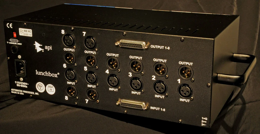
Each 500-series slot maps to a dedicated rear-panel I/O pair, typically via DB-25 (TASCAM pinout) or individual XLR and TRS connectors. We route mic-level signals through preamp modules with +48V phantom power, while line-level sources need proper impedance matching.
Cascading lets us chain one slot’s output directly into the next slot’s input, eliminating external cables and reducing noise. Understanding these signal-flow fundamentals will help you avoid common pitfalls and build more efficient routing strategies.
Demystifying 500 Series Audio Routing
The 500-series modular format, originally designed by API in the 1970s, splits audio processing into two distinct layers: the rack and the module. The chassis supplies power and backplane I/O connectivity; each module handles discrete signal processing.
Understanding this separation is critical for maintaining proper gain staging and minimizing signal degradation across your chain.
We’re routing audio through a shared infrastructure, so module compatibility with your specific chassis matters. Every patch cable connection introduces potential noise, tight routing flexibility demands intentional planning.
When we cascade preamps into EQs into compressors, we’re building series signal paths that live or die by clean I/O management.
Master these fundamentals now, and you’ll reveal noise reduction strategies, efficient patchbay integration, and hybrid workflows that actually perform.
Audio Connectors Explained: XLR, TRS, and DB-25
Because every 500-series rack routes audio through its rear-panel connectors, understanding the three primary types, XLR, TRS, and DB-25, directly impacts your signal quality and workflow efficiency.
XLR advantages center on robust balanced connections for mic and line-level signals, delivering excellent signal integrity through secure locking pins.
TRS applications typically cover auxiliary inputs and patchbay integration, using balanced 1/4-inch connections that streamline routing flexibility.
DB-25 convenience is transformative, a single 25-pin connector carries eight balanced channels, dramatically improving cable management.
Note that 500-series chassis universally follow the TASCAM DB-25 pinout standard, not Yamaha’s. Verify connector compatibility before purchasing snakes or looms. Each format serves distinct routing needs.
We recommend matching connectors to your workflow priorities: XLR for front-end sources, TRS for patching, DB-25 for multi-channel density.
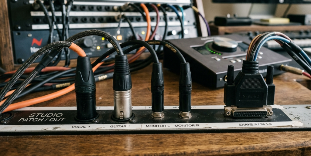
Input and Output (I/O) Basics: Getting Signal In and Out
Now that we’ve covered connector types, let’s look at how signal actually moves through a 500-series chassis. Each slot maps directly to a dedicated rear-panel I/O pair, one input, one output, unless internal routing switches override this default signal flow.
Understanding input types is critical. Mic-level signals require a preamp module, which also distributes phantom power (+48V) to condenser microphones.
Line-level and Hi-Z instrument signals need proper level matching to avoid clipping or noise-floor issues.
On the output side, output configurations typically deliver line-level balanced signal via DB-25 or TRS connections.
These balanced connections reject interference over cable runs, keeping your recordings clean. Match your downstream gear’s input sensitivity to maintain ideal gain staging throughout the chain.
Understanding Insert Points and External Processing
Keep gain staging considerations front of mind, match levels between your 500-series output and external gear’s input to avoid clipping or noise.
Combined with modular processing techniques, inserts expand your chain without compromising workflow efficiency.
Cascading Modules: Chaining 500-Series Slots in Series
When you’re building a channel strip inside your 500-series rack, say, a preamp in Slot 1 feeding an EQ in Slot 2 and then a compressor in Slot 3, cascading lets you route each module’s output directly into the next slot’s input without ever leaving the chassis.
This module integration eliminates external patch cables and dramatically improves routing efficiency.
Modern chassis like the Radial Workhorse include “Feed” switches that enable internal connections between adjacent slots with a single toggle.
Older racks require manual XLR or TRS jumpers on the rear panel to achieve the same signal flow.
Either way, the hardware advantages are clear: fewer cable runs mean less noise, tighter gain staging, and faster tracking speed. Your signal stays clean, your workflow stays streamlined.
Bus Routing and Submixing in Modular Workflows
Key applications that expand mix flexibility:
- Summing drum channels to a stereo bus through a single compressor module
- Creating parallel compression sends by splitting signal flow to wet and dry paths
- Grouping vocal tracks into a submix bus for cohesive EQ treatment
- Stereo-linking adjacent compressor slots via shared control voltage for matched gain reduction
Always verify module compatibility with your rack’s bus architecture before committing to a routing scheme.
Patchbays and 500 Series Racks: Seamless Studio Integration
This approach delivers seamless integration: every module’s I/O lives on the patchbay’s front panel, making signal-flow changes instant and repeatable across sessions.
Common Routing Pitfalls and Best Practices
Even with a well-organized patchbay and properly wired DB-25 snakes, a few common mistakes can introduce noise, damage gear, or silently degrade your signal chain.
Proper module alignment and routing strategies demand attention to these critical troubleshooting techniques:
- Ground loops and hum: Use ground lift switches to break redundant paths before reaching for EQ. Noise reduction starts at the electrical foundation.
- Double-routing signals: Engaging an internal feed switch while external cables are patched creates phase conflicts and gain structure problems.
- Phantom power on line-level modules: Sending +48V into compressors or EQs risks capacitor damage.
- Impedance mismatches between slots: Cascading modules with incompatible output/input impedances compromises signal integrity and headroom.
Frequently Asked Questions
Q: How Many Watts Does a Typical 500-Series Chassis Power Supply Provide?
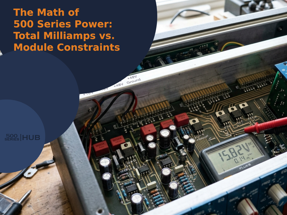
A: Most 500-series chassis power supplies deliver between 1,200-1,600mA across ±16V rails, imagine a river feeding multiple tributaries.
Power supply efficiency directly impacts module power requirements, so we’ll want headroom.
Smart chassis design considerations include robust voltage regulation issues mitigation through linear supplies, effective thermal management solutions like ventilated enclosures, and star-ground power distribution methods ensuring each slot receives clean, stable current without crosstalk or voltage sag under full load.
Q: Do All 500-Series Racks Support Stereo Linking Between Adjacent Module Slots?
A: No, not all racks support stereo linking between adjacent slots.
Stereo linking depends on your rack configuration and individual module compatibility, both the chassis and the modules must share a dedicated link bus.
Without it, you’ll compromise signal integrity when trying to gang controls.
We recommend checking design considerations for each chassis and matching modules to your user preferences, ensuring your paired units track gain reduction identically across the stereo path.
Q: Are Vintage 500-Series Modules Compatible With Modern Rack Chassis Designs?
A: Roughly 90% of vintage modules fit modern chassis thanks to standardized power connection standards, though vintage module compatibility isn’t always guaranteed.
Modern chassis design improvements mean some physical dimensions differences exist, older units may have slightly varied edge-connector tolerances.
You’ll want to follow module installation guidelines carefully, checking pin alignments before powering up.
Sound quality variations can occur due to updated power supply regulation, but we’ve found most vintage gems perform beautifully in today’s racks.
Q: What Happens if My 500-Series Rack Exceeds Its Maximum Current Draw?
A: If your rack exceeds its maximum current draw, you’ll encounter performance issues like signal degradation, unexpected noise, or modules dropping out entirely.
Poor power distribution stresses the internal supply, compromising rack safety and thermal management, overheating can damage components.
Most quality chassis offer basic module protection through current limiting, but we shouldn’t rely on that as a failsafe.
Always tally each module’s milliamp requirements before populating your chassis.
Conclusion
We’ve traced every signal path from DB-25 input to patchbay output, and now the entire 500-series routing chain should feel infinitely clearer. We’ve covered XLR and TRS connections, insert points, cascading slots, bus routing, and integration best practices.
By respecting impedance matching, maintaining proper gain staging, and keeping ground loops at bay, we’ll guarantee our modules deliver the cleanest possible signal flow every single session.
Related Articles
- Rupert Neve 542 Review: Legacy Tape Emulator!
- Radial Workhorse Cube Review: Amazing 500 Series Chassis!
- Pultec EQP-500X Review: Huge 500 Series Program Equalizer!
- SSL Six 500 Series Review: Big Channel Strip in 500!
- Rupert Neve Designs 511 Review: Amazing Mic-Pre!
- API 512c Review: Great Mic Preamp by Pioneers!
- Maag Audio EQ4 Review: Unique Modern EQ!
- 500-Series Mistakes: Common Mistakes By New Users!