Math of 500 Series Power
Picture a fully loaded 500 Series chassis humming along, until one slot’s LED flickers and your signal path turns noisy. We’ve all assumed total milliamp specs tell the whole story, but they don’t.
Per-slot current limits, voltage sag under load, and trace impedance create a hidden power budget most engineers never calculate. Understanding these constraints separates a reliable rack from a frustrating one, and the math isn’t what you’d expect.
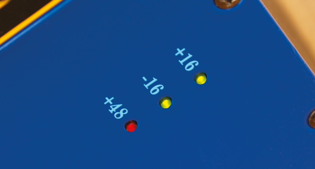
- The VPR Alliance standard allocates 130mA per slot at ±16V, regardless of total chassis capacity.
- Total rack milliamps can appear sufficient while individual slots remain constrained by edge connector trace limits.
- High-demand modules like tube preamps may exceed per-slot allocations, causing voltage sag across shared rails.
- Budget chassis with shared backplane rails risk voltage drops that degrade adjacent modules’ performance and headroom.
- Always calculate per-slot current draw individually, maintaining at least 20–30% headroom margin for reliable operation.
The VPR Alliance Standard: Decoding the +/-16V Architecture
Before the 500 series became the ubiquitous modular standard it’s today, API’s original console architecture in the late 1960s established the core voltage rails that would eventually define the format.
This historical development timeline traces directly from API’s discrete console modules to the formalized VPR specifications overview ratified by the VPR Alliance, standardizing mechanical dimensions, pinouts, and power distribution methods across manufacturers.
The baseline allocation is precise: 130mA per slot at +/-16V DC. That’s our ceiling for module design constraints.
Phantom power implementation adds 5mA at +48V per slot on a separate rail entirely. These voltage regulation techniques guarantee each slot receives clean, stable DC regardless of current draw variations between adjacent modules.
We’re working within fixed boundaries here. Every milliamp matters, and understanding this allocation framework is non-negotiable before we stack power-hungry modules into shared enclosures.
Total Enclosure Current vs. Per-Slot Limitations: The Milliamps Trap
While a chassis spec sheet boasting 2000mA total capacity looks reassuring on paper, it masks a critical bottleneck that catches even experienced integrators off guard: per-slot current limits imposed by the edge connector’s copper trace width. The VPR standard’s 15-pin edge connector physically constrains current distribution per slot, regardless of total PSU headroom.
Here’s what we need to account for:
- Connector efficiency degrades as trace temperatures rise, thermal management becomes critical when modules exceed 130mA sustained draw.
- Voltage drop across thin edge connector traces increases proportionally with current, starving high-demand modules.
- Load balancing across slots isn’t automatic; adjacent power-hungry modules compound trace heating on shared rail segments.
- Module compatibility requires verifying individual slot power allocation, not just aggregate capacity.
We can’t simply divide total PSU current by slot count. That math ignores trace-level constraints that determine real-world performance ceilings for demanding Class-A and tube-based modules.
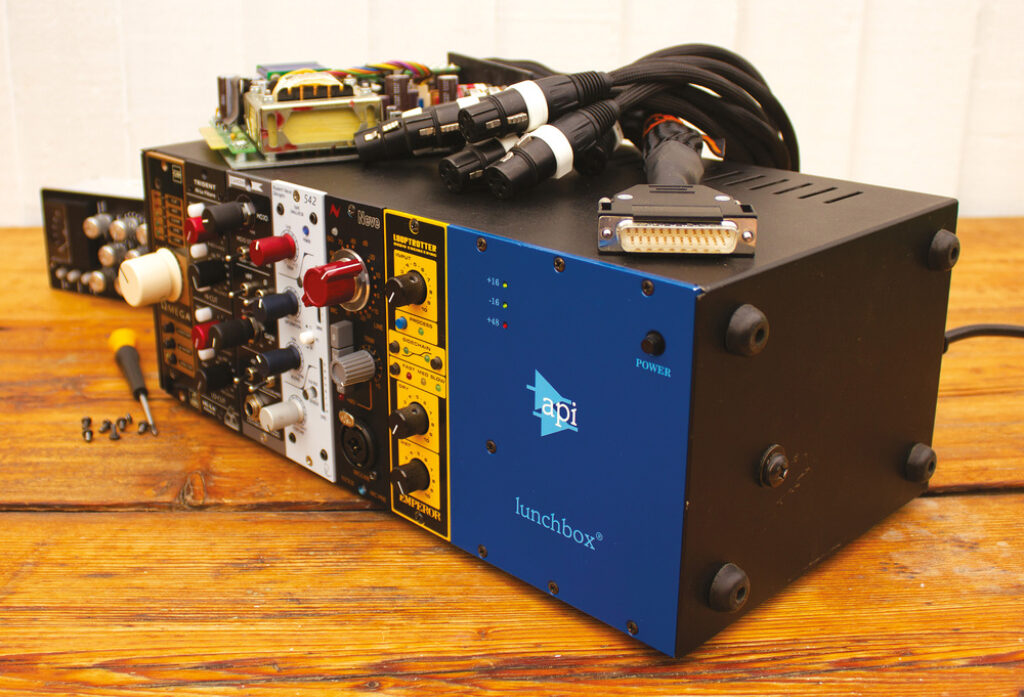
The Power Hogs: Which Modules Push the Limits?
Tube preamps demand substantial current for vacuum tube filament heating alone, before we even factor in plate voltage requirements.
Class A discrete designs run their transistors in constant conduction, burning current continuously regardless of signal presence. That’s the tradeoff for their coveted harmonic richness.
Then there’s module design featuring oversized output transformers and extensive LED metering arrays. Both add considerable milliamp draw that’s easy to overlook during rack planning.
Here’s what matters: every one of these power hogs degrades audio fidelity across your entire enclosure if you haven’t calculated total draw with adequate headroom margin.
What Happens When a Rack Suffers from Power Sag?
Voltage fluctuations across your ±16V rails directly degrade signal integrity, and the effects cascade quickly. Here’s what we’re looking at:
- Headroom loss: Clean swing shrinks as rails droop, pushing your modules into premature harmonic clipping well before their rated output.
- Rising noise floor: Insufficient power stability introduces hum and hiss as regulation circuits lose their ability to reject ripple.
- Crosstalk issues: Shared rail impedance means one module’s transient current demands modulate the supply voltage seen by adjacent slots, causing signal bleed.
- Thermal stress: Components compensating for sagging voltage run hotter, accelerating wear and degrading audio clarity over time.
We can’t highlight this enough. Maintaining that 20–30% current headroom buffer isn’t conservative engineering. It’s the baseline for professional operation.
Entry-Level vs. Premium Power: How Chassis Brands Distribute Current
Not all 500 series enclosures handle current distribution the same way, and the difference between budget and premium chassis often comes down to one critical design choice: shared vs. isolated rail regulation. Budget enclosures like the Midas L10 deliver high total current across shared backplane rails, meaning one power-hungry module can drag voltage down for every adjacent slot.
Premium racks like the Radial Workhorse and Heritage Audio OST employ isolated per-slot regulation, ensuring noise isolation between modules and stable current distribution regardless of individual draw. These design differences directly impact thermal management, crosstalk rejection, and module compatibility with high-draw Class-A circuits.
| Feature | Midas L10 (Budget) | Radial Workhorse / Heritage OST (Premium) |
|---|---|---|
| Rail Architecture | Shared backplane | Isolated per-slot regulation |
| Crosstalk Risk | High under load | Negligible |
| Recommended Headroom Buffer | 30%+ | 20% sufficient |
Step-by-Step: How to Calculate Your Lunchbox Power Budget
Knowing whether your chassis uses shared or isolated rails is only half the equation, you still need to verify that your total module draw doesn’t exceed the PSU’s rated output.
Here’s our calculation methods breakdown for performance optimization:
- Gather module ratings: Pull the +16V, -16V, and +48V mA specs from manufacturer manuals for every installed unit.
- Sum each rail independently: Total your +16V draw, -16V draw, and +48V draw separately, your PSU’s weakest rail becomes the bottleneck.
- Apply your headroom buffer: Multiply each total by 1.25 (25% safety margin) to account for inrush current and thermal drift.
- Compare against PSU power requirements: If your buffered total exceeds rated capacity on any rail, you’ll need to redistribute modules or upgrade the chassis.
This isn’t optional math. Skipping this step invites power sag, degraded headroom, and compromised fidelity across your entire signal chain.
Troubleshooting Slot Hum, Proximity Interference, and Startup Voltage Spikes
Three common failure modes plague 500 series racks once modules are seated and powered: startup inrush current spikes that trip PSU protection overcurrent circuits, electromagnetic proximity interference between adjacent slots, and persistent slot hum caused by ground loops on shared backplane rails.
When we flip the power switch, transformer-heavy modules draw massive inrush current, often 3x to 5x their steady-state consumption. This momentary spike triggers PSU protection shutdowns. The fix: stagger module insertion or install soft-start circuits.
Module placement matters critically. A tube preamp’s filament transformer radiates electromagnetic hum directly into an adjacent high-gain mic pre’s input stage, creating audio interference we can’t EQ out. We solve this by inserting a buffer slot, an EQ or compressor, between high-emission and high-sensitivity modules.
Key troubleshooting tips: swap slot positions systematically, measure per-slot voltage under load, and isolate ground paths to identify the offending module.
Frequently Asked Questions
Q: Can I Safely Mix 500 Series Modules From Different Manufacturers in One Enclosure?
A: Why wouldn’t you mix modules when the VPR standard exists precisely for module compatibility? We can absolutely cross-populate brands, but we’ve got to respect the math.
Check each unit’s power consumption against manufacturer guidelines and your enclosure’s per-slot voltage requirements.
Prioritize rack design with isolated slot regulation to maintain signal integrity. Always verify safety standards compliance and maintain that 20–30% current headroom buffer to prevent power sag and backplane crosstalk.
Q: Do 500 Series Modules Work With Rechargeable Battery-Powered Portable Enclosures?
A: Battery-powered portable setups can run 500 series modules, but you’ll face serious voltage requirements, sustaining stable +/-16V DC under load demands robust battery efficiency engineering.
Module compatibility varies wildly; high-draw Class-A units will drain cells fast, so we’d recommend calculating total power consumption per slot.
Your enclosure design must incorporate regulated DC-DC conversion to prevent sag.
Realistic usage scenarios include field recording with low-current preamps, where maintaining that 20-30% headroom buffer remains critical.
Q: Can a 500 Series Rack Be Daisy-Chained to Expand Total Available Slots?
A: You can’t truly daisy-chain 500 series enclosures, there’s no standardized rack expansion protocol in the VPR spec. Each enclosure operates independently with its own power distribution and power limitations.
Running modules across separate units means you’ll manage module compatibility and signal integrity through external patching, not a shared backplane. The daisy chain risks include ground loops and voltage inconsistencies between enclosures.
Ultimately, enclosure design dictates your slot ceiling, plan your milliamp budget accordingly.
Q: Are 500 Series Modules Compatible With European 230V Mains Power Without Modification?
A: Like Edison’s lamplighters adjusting to AC, we must address voltage compatibility head-on: 500 series module design operates on DC rails supplied by the enclosure’s PSU, not mains directly.
Your power requirements are handled at the enclosure level. Most premium enclosures include universal transformer options (100-240V), meeting European standards and safety regulations without enclosure modifications.
We’re simply ensuring the PSU accepts 230V, the modules themselves don’t care.
Q: How Often Should the Internal Power Supply Capacitors in Enclosures Be Replaced?
A: We recommend replacing internal power supply capacitors every 5–7 years, though capacitor lifespan depends heavily on heat dissipation efficiency within your enclosure design.
Degraded caps compromise voltage stability, tanking signal integrity and module reliability across your backplane.
If you’re running high-draw Class-A modules, inspect sooner, electrolytic caps dry out faster under thermal stress.
Proactive power supply maintenance prevents subtle headroom loss and noise floor creep before they corrupt your recordings.
Conclusion
We’ve peeled back the curtain on the 500 Series power equation, and the takeaway’s clear: total milliamps on a spec sheet don’t tell the whole story. Per-slot current ceilings, voltage sag under load, and trace impedance all conspire against signal integrity when we’re not budgeting carefully.
By auditing each module’s draw, load-balancing across slots, and investing in robust PSU architectures, we’ll keep our rails clean and our signal path uncompromised.
Related Articles
- 500 Series Audio: Pro Audio Equipment for Every Home Studio!
- History of 500 Series Format: How 500 Series Modules Came!
- Understanding 500 Series Chassis: A Complete Guide
- 500 Series Vs Standard Rack Gear: Key Differences & Comparison!
- Rupert Neve 542 Review: Legacy Tape Emulator!
- Elysia xfilter 500 Review: Pro Audio Stereo Equalizer!
- Chandler tg2 500 Review: 500 Series Microphone Preamp!
- Radial Workhorse Cube Review: Amazing 500 Series Chassis!
- SSL G Bus Review: Great 500 Series Compressor Module!