Introduction
In a 500 series rack, your audio signal enters through the chassis backplane’s XLR input pins, passes through gold-plated edge connector contacts, and hits the module’s input stage for impedance-matched reception.
The module processes the signal, applying gain, EQ, or compression, then routes it back through the edge connector to the backplane’s XLR output pins. When it comes to 500 series signal flow, there are several options that you can go for and we all covered them below in this text.
Each connector junction introduces contact resistance and capacitive coupling that shape high-frequency response. Well, now its time to check this procedure out and ease it for everyone that needs to understand this process.
- Audio enters through the chassis backplane’s XLR input pins and routes to the module’s edge connector for processing.
- The signal passes through input stage, processing modules (EQ, compression), and exits through the output stage.
- The backplane connector introduces contact resistance and capacitive coupling that can affect high-frequency response.
- Module order significantly shapes the result: preamp-first chains feed into EQ and compression in various sequences.
- Processed signal exits via the edge connector to the backplane’s XLR output, routing to recording or monitoring systems.
500 Series Signal Flow Basics: Input to Output
Every 500 series module follows a fundamental signal path: audio enters through the chassis backplane’s XLR input pins, routes to the module’s edge connector, passes through the module’s processing circuitry, and exits back through the edge connector to the backplane’s XLR output pins. This complete signal flow defines every 500 series signal transaction.
Understanding input to output routing means tracing each node in the signal chain. The backplane distributes power rails and audio simultaneously, while the edge connector’s pin assignments dictate how the module intercepts and processes the signal flow.
We’re looking at a standardized architecture where impedance matching, grounding topology, and gain staging all converge at precisely defined junction points. Mastering this signal path reveals modular design possibilities that push beyond conventional processing frameworks.

How Audio Enters a 500 Series Rack
Before any module processes a single sample, the audio signal must first hit the rack’s rear-panel XLR input jacks. These are the system’s primary ingress points. Each XLR connector carries a balanced audio signal through the chassis backplane, where signal routing directs it to the corresponding module slot.
Here’s how the 500 series rack ingress chain works:
- Mic or line-level source connects to the rear XLR input via balanced cabling.
- The chassis backplane receives the signal and maps it to the assigned slot’s edge connector.
- Pin-to-pin signal routing guarantees proper hot, cold, and ground continuity throughout.
- The module’s input stage taps the routed signal for processing.
We’re fundamentally leveraging the rack as a centralized signal distribution hub before any gain staging occurs.
What the Backplane Connector Does to Your Signal
The backplane connector introduces three critical signal-path variables we can’t ignore: contact resistance, capacitive coupling between adjacent pins, and ground-plane integrity across the edge connector interface. Each module’s analog signal passes through gold-plated contact points where micro-ohm resistance variations directly affect voltage transfer ratios.
Within 500 series modules and chassis, the connector serves as the routing nexus, mapping input, output, power, and ground rails across a standardized pin configuration.
We’re dealing with signal-carrying pins positioned millimeters from ±16V supply rails, making crosstalk management non-trivial. The connector’s impedance characteristics shape high-frequency rolloff before the module’s circuitry even engages.
Understanding these interactions lets us optimize signal integrity at the mechanical level, pushing analog signal performance beyond what passive connector design traditionally permits.

Series vs. Parallel Signal Flow in 500 Series Racks
When we route audio through a 500 series rack, the chassis’s internal bus architecture dictates whether each module processes signal independently or feeds directly into the next slot’s input, parallel vs. series signal flow.
In series configuration, modules cascade sequentially, forming a complex signal path where each processor’s output drives the next stage’s input, a true analog signal chain.
Parallel mode routes identical source signal to all slots simultaneously, preserving independent processing paths.
Key distinctions between configurations:
- Series: Signal degrades cumulatively through each module’s gain staging
- Parallel: Each slot receives pristine source, minimizing cascaded noise
- Series: Enables sequential EQ-to-compressor chains within the chassis
- Parallel: Supports summing workflows across multiple 500 series rack modules
Your routing choice fundamentally shapes the signal’s integrity and processing topology.
How Modules Pass Signal From Slot to Slot
Understanding series vs. parallel topology at a conceptual level only gets us halfway, we need to examine the actual electrical handoff between slots. Each 500 series module communicates via edge connector pins on the chassis, where modules take up one slot and pass signal through dedicated send/return paths.
| Parameter | Detail |
|---|---|
| Handoff Method | Edge connector pin-to-bus routing |
| Signal Path | Balanced differential between adjacent slots |
| Impedance Target | Matched low-Z for ideal signal transfer |
The chassis and modules maintain signal integrity through standardized pin assignments. When we cascade a rack’s slots in series, each module’s output feeds the next slot’s input via backplane traces. This architecture guarantees minimal degradation across the signal chain.
Choosing Your 500 Series Chain Order: Preamp, EQ, and Compressor
Three modules, preamp, EQ, and compressor, form the core 500 series signal chain, and the order we rack them in directly shapes gain staging, harmonic content, and dynamic response at every subsequent stage.
- Preamp → EQ → Compressor: We sculpt the spectrum before dynamics processing, meaning the compressor reacts to the shaped signal, boosted frequencies trigger gain reduction more aggressively.
- Preamp → Compressor → EQ: We compress the raw captured signal first, then apply tonal correction post-dynamics, preserving a more uniform compression response.
- EQ → Preamp → Compressor: Rare, but useful when driving a preamp’s input stage with pre-shaped frequency content for targeted harmonic saturation.
- Preamp → Compressor → EQ → Compressor: A dual-compression topology enabling serial dynamics control with tonal intervention between stages.
Each configuration yields distinct transient behavior and spectral weighting.
Common 500 Series Signal Flow Mistakes to Avoid
Even with a well-considered chain order, missteps in gain staging, impedance matching, and module placement can undermine the entire signal path.
In any 500 series setup, we must verify that modules draw within the chassis’s PSU current limits. Overloading a 500 series chassis introduces noise floor degradation and transient sag across every slot.
When we mix and match modules from different manufacturers, impedance mismatches between outputs and inputs create signal flow anomalies: level drops, high-frequency rolloff, or phase inconsistencies.
Don’t engage phantom power on slots feeding line-level modules, it’ll stress components not designed for that DC offset.
Always route signal sequentially through adjacent slots to minimize crosstalk and cable-induced capacitance. Validate each stage’s nominal operating level before committing to a chain topology.
Reordering Modules to Shape Your 500 Series Sound
Because every 500 series module imparts its own harmonic signature, transient response, and impedance characteristics, swapping the order of processors in our chain fundamentally reshapes the signal’s tonal and dynamic profile.
Consider these reordering strategies:
- Pre-EQ compression: Driving a compressor with shaped frequency content alters gain reduction behavior, targeting specific spectral energy.
- Post-EQ compression: Compressing first preserves the EQ’s tonal sculpting without dynamic interaction artifacts.
- Saturator-first topology: Feeding harmonic-rich signal into subsequent modules excites resonant filter stages differently.
- Parallel routing via summing: Splitting signal across parallel module paths before recombining yields phase-coherent tonal blending.
We’re not just processing, we’re architecting impedance-dependent interactions between stages.
Each permutation yields distinct transient envelope shaping and spectral density redistribution across our signal path.
Frequently Asked Questions
Q: Can 500 Series Modules Be Used With Digital Audio Workstations Directly?
A: No, 500 series modules can’t interface directly with your DAW, think of them as analog islands requiring a bridge to the digital mainland.
We need an audio interface with AD/DA conversion to translate their analog signal path into digital streams.
We’re routing module outputs into our interface’s line inputs, converting that analog voltage to PCM data, then capturing it in our DAW.
The interface is our essential gateway between these two worlds.
Q: Do All 500 Series Modules Consume the Same Amount of Power?
A: No, they don’t. Each 500 series module draws different current from the ±16V and +48V rails depending on its circuit topology.
Tube-based modules and high-headroom preamps typically pull considerably more milliamps than passive EQs or simple compressors.
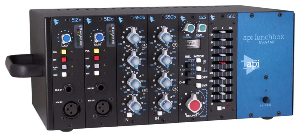
We need to monitor our chassis’s total power budget carefully, exceeding the lunchbox’s PSU capacity causes voltage sag, degraded transient response, and increased noise floor across every module in the signal chain.
Q: Are 500 Series Modules From Different Manufacturers Always Compatible With Each Rack?
A: Not always, and here’s where it gets tricky. While the VPR Alliance standard defines pin assignments, power rails, and form factor, we’ve encountered edge cases where certain modules draw excessive current, exceed depth tolerances, or implement non-standard grounding schemes that conflict with specific chassis designs.
We recommend cross-referencing each module’s power consumption, physical dimensions, and I/O topology against your rack’s specifications before committing to any signal chain integration.
Q: How Does Cable Quality Affect 500 Series Signal Flow Performance?
A: Cable quality directly impacts signal integrity across your 500 series chain.
We’re talking about capacitance, shielding effectiveness, and conductor purity, all influencing noise floor, high-frequency rolloff, and crosstalk rejection.
Poor cables introduce impedance mismatches that degrade your module’s output stage before signal even hits the next gain block.
We recommend low-capacitance, quad-shielded interconnects with gold-plated connectors to preserve the transient detail and dynamic range your premium modules deliver.
Q: Can 500 Series Racks Introduce Noise When Slots Are Left Empty?
A: Yes, empty slots can absolutely inject noise into your signal path, because apparently, leaving a gaping hole in your audio chain is a brilliant engineering strategy.
Without blank panels or dummy cards, unterminated bus connections act as antennas, coupling EMI and crosstalk across the backplane.
We’re talking degraded SNR and unwanted artifacts bleeding into adjacent channels.
Always populate unused slots with blanking modules to maintain proper impedance matching and shield your signal integrity.
Conclusion
We understand signal flow diagrams can feel overwhelming, but once you’ve traced your audio from the XLR input through the backplane’s edge connector, across each module’s discrete gain stage, and out the summed bus, it clicks.
We’ve mapped every node: preamp impedance bridging, inter-slot normalling, and series-chain topology. Don’t let connector pinouts intimidate you. Grab your modules, rack ’em deliberately, and let the signal path dictate your sonic decisions.
Related Articles
- 500 Series Audio: Pro Audio Equipment for Every Home Studio!
- History of 500 Series Format: How 500 Series Modules Came!
- Understanding 500 Series Chassis: A Complete Guide
- 500 Series Vs Standard Rack Gear: Key Differences & Comparison!
- Rupert Neve 542 Review: Legacy Tape Emulator!
- Elysia xfilter 500 Review: Pro Audio Stereo Equalizer!