Introduction
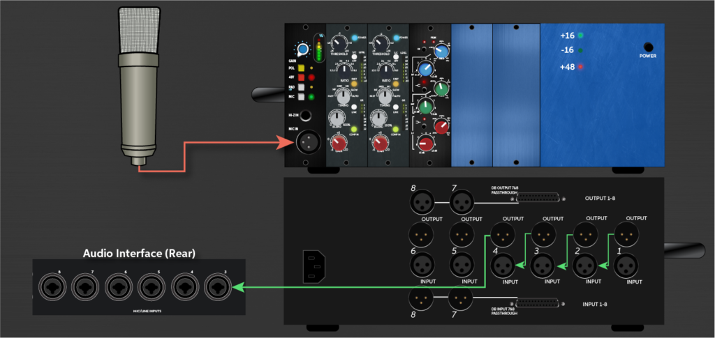
Many engineers overlook that improper grounding in a 500 Series setup can introduce noise even if using balanced cables. Wiring a 500 Series rack to a DAW requires precise attention to signal flow: mic > rack input > preamp/EQ/compressor modules > chassis output (TRS/DB25) > audio interface.
Each connection impacts audio quality and workflow efficiency. Understanding module order and return routing is critical for seamless integration, and that’s why we are going to show you how to wire 500 series with DAW the right way!
Key Takeaways
- Connect your microphone to the 500 Series chassis input using balanced XLR cables for clean, noise-free signal capture.
- Route audio from your interface’s line output to the 500 Series module line input with balanced TRS or DB25 cables.
- Use a patchbay for flexible routing between your interface, 500 Series modules, and other outboard gear.
- Return the processed signal from the 500 Series output back into your interface’s line input, matching gain levels and disabling phantom power.
- Organize cables carefully, ensure proper grounding, and verify power supply stability to prevent noise and signal loss.
What Gear Do You Need to Connect 500 Series to Your DAW?
Before connecting a 500 Series rack to a DAW, gathering the right gear for each stage of the signal path is essential. Start with a quality microphone, ensuring ideal microphone placement for source capture. Use balanced XLR cables from mic to the rack’s front panel.
The 500 Series chassis requires a reliable power supply; verify current ratings and redundancy for uninterrupted operation. Use TRS or DB25 cables for output to your audio interface.
Implement cable management tips: use color-coding, short runs, and secure bundles to reduce noise and confusion. Prioritize gain staging at each module to maximize headroom and minimize distortion.
For efficient signal flow troubleshooting, maintain a clear diagram showing mic input → chassis → modules → interface, enabling rapid isolation of problematic links.
How to Hook Up Your 500 Series Modules and Patchbay
Once the required gear is assembled, connect the microphone’s balanced XLR cable to the 500 Series chassis panel input.
Then route the internal signal through the installed modules in the desired order. Ideal module placement is critical, preamp first, followed by EQ or compressor modules, to maintain logical signal flow.
Secure the chassis to a stable power supply, ensuring all slots receive adequate voltage and current. Integrate a patchbay using TRS or DB25 connectors to streamline external routing and recall.
Use precise cable management to minimize interference and signal degradation. Apply grounding techniques such as chassis – grounding and shielded cables to prevent hum or noise artifacts.
Diagram the signal path: Mic → Chassis Input → Module Chain → Patchbay Output → Interface Input.
Sending Audio From Your DAW to 500 Series Hardware
After establishing the initial signal path from microphone to DAW, routing audio from the DAW back through 500 Series hardware enables outboard processing during mixing or re-amping.
To achieve this, connect a DAW/interface line output to the 500 Series module’s line input using balanced TRS or XLR cable types to maintain ideal signal integrity.
Confirm the module’s power requirements are met by the chassis. Signal flow should be clearly mapped: DAW output → interface output → 500 Series line input.
Attentively manage gain staging to avoid distortion or noise, adjusting DAW output and module input levels accordingly.
Verify impedance matching between the interface output and 500 Series input to prevent signal loss. This configuration supports advanced analog processing, releasing creative workflow possibilities.
Routing Processed Audio Back Into Your DAW
Although the processed audio has passed through the 500 Series hardware, it must be routed back into the DAW for further editing or mixing. Connect the 500 Series output to your audio interface’s line input, ensuring ideal signal flow.
Maintain proper gain staging to avoid unwanted noise or distortion. Level matching between the hardware output and interface input is vital for preserving sonic integrity. If any modules require phantom power, disengage it on the interface to prevent conflicts.
Confirm the monitor setup allows you to reference the returned signal accurately. The following table outlines essential routing considerations:
| Step | Key Consideration |
|---|---|
| Output Connection | Balanced cabling |
| Gain Staging | Avoid clipping |
| Level Matching | Unity gain |
| Phantom Power | Disable on interface |
| Monitor Setup | A/B processed signal |
Setting Up Your DAW for External 500 Series Processing
Because most DAWs handle external hardware integration through dedicated routing menus, users should first locate the I/O settings or external insert section within their software.
Assign the interface’s line outputs to send audio to the 500 series chassis, ensuring interface compatibility and balanced signal levels.
For vintage gear, confirm that the DAW’s send and return channels match the hardware’s requirements. Always double-check power supplies to avoid introducing unwanted noise or interference.
Construct a clear signal flow diagram: DAW output → interface line out → 500 series input → module processing → 500 series output → interface line in → DAW return.
Minimize ground loops by using balanced cables and grounding points. This setup streamlines creative routing, merging classic analog tone with modern digital workflows.
How to Fix Common 500 Series and DAW Connection Problems
Even with careful setup, users may encounter signal issues or routing errors when integrating 500 series modules with a DAW. Troubleshooting begins with verifying microphone grounding to prevent hum and interference.
Improper cable management can introduce noise or crosstalk, so align cables away from power supplies and digital lines. Power supply issues often manifest as module instability or reduced signal clarity; confirm all modules receive adequate and consistent voltage.
If phantom power is needed, ensure the DAW interface or chassis supplies it correctly, as improper phantom routing can damage sensitive components. For persistent signal clarity problems, trace the signal flow: mic to chassis, module, then interface, and isolate each stage for testing.
| Problem | Symptom | Solution |
|---|---|---|
| Microphone grounding | Hum/interference | Check ground paths |
| Power supply issues | Module drops, distortion | Verify voltage, swap supply |
| Cable management | Noise, crosstalk | Separate, label, reroute |
Conclusion
Wiring a 500 Series system to a DAW is like plotting a signal’s journey through a high-end circuit city. Each module a landmark, every cable a thoroughfare. With tight connections, balanced cables, and vigilant grounding, engineers map pristine audio from microphone to interface.
Once the DAW’s routing is dialed in, the signal flows seamlessly, free from noise or interference. Mastering this technical choreography lets creativity glide, letting hardware and software dance in perfect sync.
Related Articles
- 500 Series Audio: Pro Audio Equipment for Every Home Studio!
- History of 500 Series Format: How 500 Series Modules Came!
- Anatomy of 500 Series Module: Inside the Design!
- Understanding 500 Series Chassis: A Complete Guide
- Common 500 Series Module Types: Big Buying Guide!
- 500 Series for Home Studio: Big Tips, Workflow and Setup!
- Pros and Cons of 500 Series Audio: Choose Wisely!